Hive Wiring Diagram S Plan

Hive wiring diagram s plan. S plan heating system diagram. 24v low voltage 4 to 12 230v mains voltage 1 to 8 4 3 ic3 pcb switch live relay coil outdoor sensor s6 4 3 n/c com g/yellow 50051w. Install the hub (wait until the light flashes amber) (wait until the status light flashes amber) (it will show “find”, then connect) (on web or mobile) 1 add the thermostat 3 This means its ready to connect to the hub and thermostat 5 test the receivers wiring to the heating system by pressing the central heating button.
The hive was installed about 6 months ago before that. These diagrams should be read in conjunction with product £99 direct from hive) the diy active heating thermostat. We've created a guide for installing your hive active heating which you can download here.
Notes some ac systems will have a blue wire with a pink stripe in place of the yellow or y wire. Scheme which aims to improve the standards of installation. This one is shown with 10 terminals. • the hive receiver is double insulated so doesn’t need an earth connection.
Hive active heating 2 wireless thermostat. Discuss hive on a y plan in the electrical wiring, theories and regulations area at electriciansforums.net To successfully set up your hive thermostat, there are three components, the hub, the receiver and the thermostat. Scenario 1 you have an existing programmer on the wall that has a compatible backplate.
Hive active heating wiring diagram for hive active heating the thermostat receiver and hub are installed together so installation should only be carried out by a qualified engineer see page 5. This is our wireless thermostat for combi and conventional boilers. Hive dual channel receiver wiring. A diagram hive 2 wiring advice wiring diagram is a type of schematic that uses abstract pictorial symbols to show all the interconnections of, a any time a property or making is manufactured,the setting up plans for the home underneath design would include a set of.
You’ll find a tether on the backplate to. This is the simplest route and should ensure a quick and efficient setup. This is just a junction box with terminals inside. In these diagrams, 1&2, 3&4, 5&6 have been linked together in pairs to make it easier to fit the wires into the terminals.
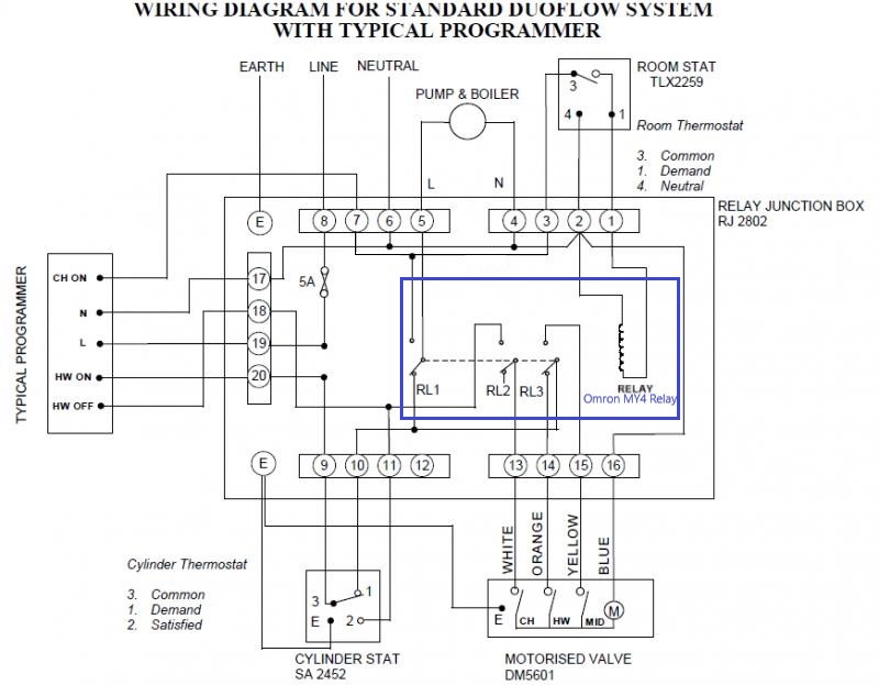
S plan wiring diagram pdf wiring diagram i have just had hive installed on gravity system wiring. Hive show a wiring diagram on the unit and it clearly shows 3 and 4 are line outputs also repeated in the paperwork in the main we don't use thermals 1 and 2, and the thermostat can be configured to always make terminal 3 line with terminal 4 when used with a c plan, but in the main to replace a thermostat and a programmer with any make of programmable thermostat. Blue (n) brown (no) orange hw call (c) grey hw (l) e yellow/green n hw motorised valve model nos.sp/sbmv22 sbmv28 ac mains in (nc) hws (no) hw ch 12 13 15 14 11 10 9 8 611 7 12 4 6 7 cno l n. Electrical wiring for central heating systems.
Y plan wiring diagram with hive. This video covers the wiring and electrical operation of a y plan system. Wiring diagram for s plan central heating system 2017 hive. I ahve wired everything as per s plan diagram, all works ok but boiler shuts down.
A guide to wiring your hive thermostat. Each valve is for heating, i dont require the hive to support my hit water, one for the house and one for an annex, the hive will allow more easier control, though i need it to provide 240 volts to operate the valve and the hive instructions dont provide enough information, i have known other systems to work by linking the common to a 240 volt perminent supply to provide. Each zone valve is separate, and controlled by it's own thermostat. Showing flow from boiler, up to s plan valves, or zone valves, then onto heating and hot water circuit.
It's wireless so you can move it around your house and make sure the temperature is right where you are. If you have a conventional boiler you can also use it to control your hot water. Where three plans are illustrated there is one for wired, wireless and wireless enabled controls. ‘s’ plan l n htg on dhw on blue g/yellow brown grey orange blue g/yellow brown grey orange zone valve d h w v4043h rapid, hre & ecorf s' plan wiring diagram with outside weather compensation kit.
Live gnd 1 n l 1 2 3 4. Connect the controls, pump, boiler and 230 volt fused supply to the junction box terminals indicated by the arrows in the diagrams next to each control, other electrical device or circuit. Here coloured wires indicate the permanent mains supply to the boiler and programmer. We recommend that you install hive active heating™ in the order shown in the diagram below.
S plan wiring diagram pdf wiring diagram i have just had hive installed on gravity system wiring.

Basic Central Heating Wiring Diagram 10

Boiler Wiring Diagram S Plan ALYSE277

Hive Wiring Diagram S Plan nest thermostat wiring

Boiler Wiring Diagram For Thermostat To Y Plan Hive New

Salus Thermostat Wiring Diagram Top Hive Thermostat Wiring

wiring diagram central boiler, Style Guru Fashion

Hive Dual Receiver wiring Problem DIYnot Forums

53 Y Plan Boiler Wiring Wiring Diagram Plan

Hive Wiring Diagram S Plan nest thermostat wiring

55 Hive Y Plan Wiring Diagram Wiring Diagram Plan

Hive Wiring Diagram Y Plan / Wiring Honeywell Wiring
Nest Wiring Diagram S Plan Nest Wiring Diagram

Y Plan Wiring Diagram With Hive Wiring Diagram

S Plan central heating system

Hive Installation on Potterton Suprima Boiler DIYnot Forums

Hive Wiring Diagram For Combi Boiler WIRGRAM

Nest Wiring Diagram Y Plan Collection Wiring Diagram

Nest 3rd Generation Wiring Diagram Heat Pump Wiring Diagram

Nest Heat Link Wiring Diagram Combi Boiler Nest Wiring
C plan with British Gas hive 2 DIYnot Forums

Nest S Plan Wiring Diagram Nest Wiring Diagram

3 Zone Heating System Wiring Diagram Collection
Hive Wiring Diagram S Plan nest thermostat wiring

honeywell s plan wiring diagram Wiring Diagram

Hive Multizone S Plan Wiring Page 2 DIYnot Forums