Hot Runner Controller Wiring Diagram

Hot runner controller wiring diagram. Hot runner product handbook v18 0 book. The input thermocouple type is j type or k type. 1/13) control circuit 2 = pin 2/7 (2/10; Smart series mainframe connector wiring standard:
Hrtc is the abbreviation of hot runner temperature controller, also known as htc (hot runner controller). If using a control unit other than the one specified by us, the wiring diagram is no longer valid. For first aid contact your medical / safety representing. Reference the wiring diagrams below to connect the pulse control system to ac power.
T r amt blsea controlled temperature increase • diagnosis/wire test. Huskey hot runner wiring diagram. Dme mainframes and modules comply with Hot runner systems 4.02 overview ahot runner system is used to maintain a molten flow of plastic from the molding machine nozzle to the gate of a plastic injection mold.
Wire guard a) retainer plate for connection box b) wire guard 3 / 4 Control circuit 1 = pin 1/6 (1/9; Always connect the “ground” wire first to avoid electrical shock or short. ** all wiring configurations ** european standard 3 phase wye primary 1 phase open delta primary
For any work on the hot runner system, check that the system is properly grounded. All wiring diagrams can be referenced at the end of this section. Instructions for wiring, installing, and troubleshooting the temperature controllers are in the manual supplied with the mainframe. Control circuits as per the günther standard:
All wiring diagrams can be referenced at the end of this section. Input power wiring diagrams (option b) option b. Plate design for husky manifold systems. Page content text smart series ® wiring diagram for dme hot runner molding system with high power smart series ® mold connectors.
Manual output and arrow buttons, open valve gate manually and set the time button function Based on the wiring diagram, wire each heater and thermocouple to the correct junction in the mold box and then from that junction to the back of the heater or t/c connector point. All wiring diagrams can be referenced at the end of this brochure. If using a control unit other than the one specified by us, the wiring diagram is no longer valid.
1) close the injection mold. Connection box shown on the right there are the basic components of wire guards which are mounted to the hot runner system. Section reference getting started.4 unpacking your pulse.4 what’s included.4 Customer must insure of proper connection to earth ground!
Eliminates the cold runner that would be either scrap or require regrind. (1) control pcb unit : The temperature settnig range is 0~450℃ (32~842℉). Software power on/off button and operation mode button.
The mold box is a transition from the hot half to the heater and thermocouple cables. Generally, there are cartridge heaters and coil heaters in the manifold. Note that lines rl/1 and sl/2 are connected through the circuit breaker to the appropriate terminal strips. The hot runner temperature controller adopts an adaptive control method combining fuzzy control and pid control, and the temperature control accuracy can reach 1℃.
(4) keypad pcb unit : Page content text smart series ® 156. Smart series ssh & esh user manual: Smart series mold connection wiring 5 8 & 12 zone 15 amp:
Husky injection molding systems ppt. Dme mainframes and modules comply with Smart series input power wiring diagrams option a: Note that lines rl1 and sl2 are connected through
2) switch off temperature control of the hot runner system and the control system of the injection molding machine. Power, mpu (micro processor unit), i/o (input/output) (2) display pcb unit : Design of the wire guards are done according to customer specification. Fnd (flexible numeric display, 7 segments display unit) (3) power pcb unit :
The configuration, these diagrams will help ensure safe and proper connections. The configuration, these diagrams will help ensure safe and proper connections. Hot runner & control systems. Smart series ssh sha esh:
Smart series ssm & ssa guide: Shown on the right there are two examples for conection boxes as they are used for hot runner systems. Hot runner & control systems. In the off or “o” position.
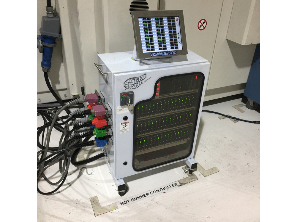
Hot runner mold temperature control system & accessories visions 3000 computerized systems.

Special Report The right cabling boosts hotrunner

Controlling Your Hot Runner Manifold System MoldMaking

Widely Used Industrial Manufacturer Plastic Injection Yudo

Hot Runner Controller Mainframe System (GMF) Nickerson

Thermozones Hot Runner Control System

9.3. Intake Air Temperature

Low Price Directselling,Ibs 8 Zones Plastic Injection Mold

Hot Runner temperature controller Test01 YouTube

Hot Runner Controllers Heater Knowledge Yancheng
Complete Package Professional PID Programmable Control (50

Hot Runner Cables & Connectors MPI Morheat
ITC International Temperature Controls Streamline

Anole Hot Runner Controller

Hot runner control system for plastic industry Changzhou

Hot Runner Controller TCS10 ESTTHERM™ eBay

Stand alone Hot Runner Controller 1 or 2 zones Nickerson

Hot Runner Temperature Controller

Smart Hot Runner Controller 1 or 2 zones Hitcontrols

4 Runner Wiring Diagram Iron Edge Diagram

TMS001 Hot Runner Sequential Controller Yikai

Smart Hot Runner Controller 1 or 2 zones Hitcontrols

Hot Runner Mainframe Controller Nickerson PMS online store

Repair Guides Overall Electrical Wiring Diagram (2004

Hot Runner Temperature Controller 4 Zone Hot Runner

Hot Runner Mainframe Controller Nickerson PMS online store